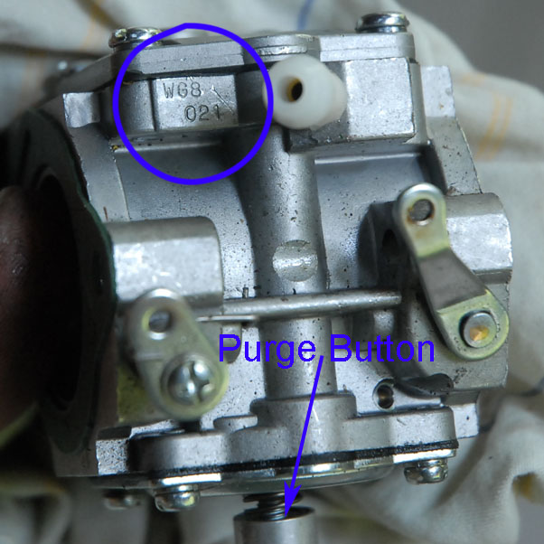
This shows the disassembly of Walbro WG-8 carb that was
supplied
with the Radne Aero 120 on a Mosquito NRG. Note the purge
button
on the diaphram cover - this has apparently been discontinued on later
models, but is very useful for bleeding air from the fuel lines.
Apparently some units are now shipping with the WG-10 carb.
A comparison of part numbers on Walbro's website shows that they are nearly identical. The only differences I could find were:
- The WG8 lists a Nozzle Jet part 112-3051, the WG10 has this blank
- Metering cover screws(4) - The WG8 uses 96-589 and the WG10 uses 96-603
So presumably the information on this page will apply to the WG-10 in most respects. There is also a WG-12, which uses the
same repair kit, which implies a great deal of similarily for that model as well.
This exploded parts diagram is for the WG-8, but applies to the WG-10 (with slight exceptions noted above).
Thanks to Greg Dewenter for the edited form of the parts diagram below (which is better than the one
currently on Walbro's parts page):
Parts are available on
Walbro's Website
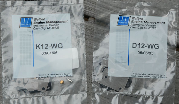
There are two repair kits available. The K12-WG has almost
all
the parts, including needle, fuel strainer screens, etc. Note
that it does
not
have
a metering spring. The D12-WG has just the gaskets and
diaphragms
(metering and pump).
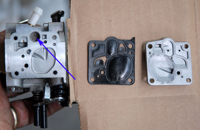
The figures below show the operation of the fuel pump and the fuel pump
diaphram on the WG-8. Air impulse pressure on one side of the diaphram
serves to pump the fuel on the other side. The blue arrow
points
to the final fuel filter screen (which has collected some debris in the
photo). The operation diagrams and explanations on this page
are
excerpted from theWalbro Service Manual:
http://wind-drifter.com/technical/WalbroServiceManual.pdf
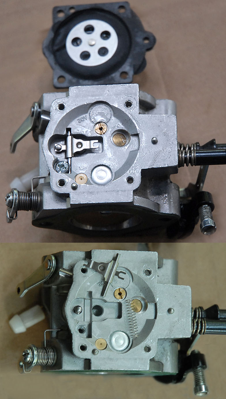
The figures below describe the fuel
metering system and show 2 stages of dis-assembly:
Walbro has a gage for setting metering lever height, as shown below.
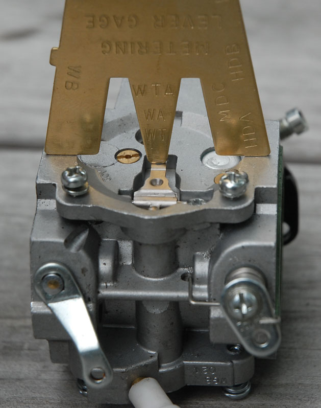
You can buy the gage from Walbro, or you can make your own.
If
you download
WalbroGage.pdf
you
can print out an exact scale image of the gage (be sure to turn off
page scaling when you print it). If it does not print
correctly,
there is a ruler in the picture you can use to scale it. The
dimensions are also included.
NEW
INFO - see discussion below on different diaphragms.
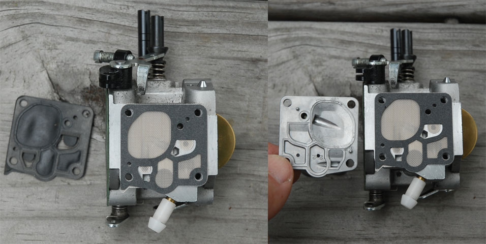
The figure below shows the installation of the metering
diaphragm and
cover.
Note
that on
this side the gasket goes on first, then the diaphragm.
(this is the opposite of the pump side). This is the newer
style
diaphragm, which does not have the interlocking tang for the metering
lever.
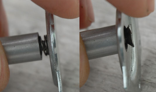
The following image shows the difference in the two diaphragm
styles
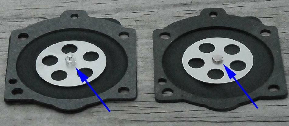
If you have the style with the interlocking tang, be sure it is
properly
engaged in the metering lever slot. When I bought the K12-WG
repair kit from a Walbro distributor, it did not have the tang (on the
right in the above image). The replacement kit I ordered from
Radne (part #32155) had the diaphragm on the left (in a bag dated Mar
'05 - so perhaps it was old stock)
Important: The
two diaphragms have different button heights, which will affect the
setting of the metering lever. The height I measured is
nearly 1
mm (0.94 mm is what I measured being as precise as I could). The button height on the interlocking button (not counting the
interlocking tang) is about 2 mm, while on the plain button it is only about 1 mm.
The
question is, which diaphram is the gage designed for? I
think
perhaps the button version (on the left), but that is
only a guess.
Responses from Walbro (US and Australia) were less than
totally
enlightening. Yes, there is a difference, yes, it should be
compensated for, no, it's not that critical, they are trying to
standardize settings, and so on. If you have information to
clear
this up, please contact me. But be aware that this is
currently
unresolved. Having said that, this is my current
Best Guess at the
correct settings:
- Diaphragm with tang
- set using the Walbro Gage WG tang (1.7 mm below the body surface). This is approximately flush to the
carb body surface
- Diaphragm
without tang - my logic says the lever should be ~0.95mm higher to
operate the same, therefore the lever should be set ~0.75mm below the
body surface.
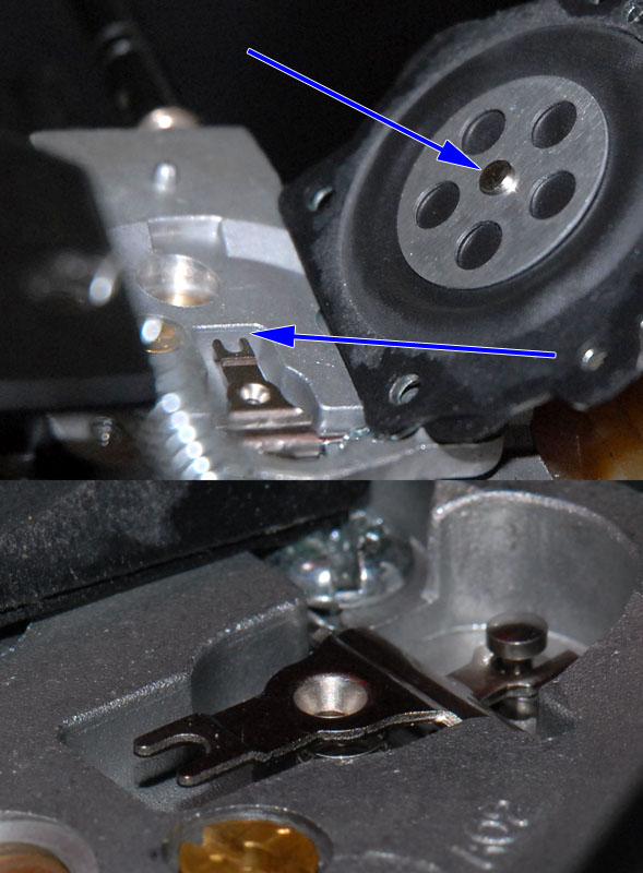
- The displacement of the metering valve is limited by the metal plate on the diaphram. When this contacts the carb body, no
further movement is possible. The WB gage sets the tang approximately even with the carb body. That means there is about 2mm
of movement possible with the interlocking tang. With the 1 mm high plain tang, only 1 mm of movement is possible. Maybe
that is enough, but erring on a low setting for the lever certainly risks fuel starvation.
This image further clarifies the travel limiting effect of the metal plate on the carb body:
If you find information which
is more authoritative than this, use it instead.
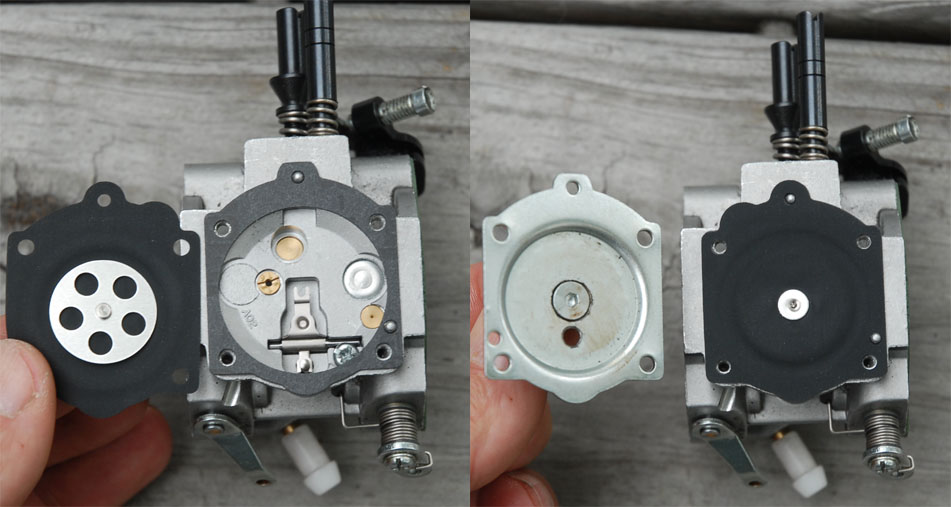
On the pump side the installation order between diaphragm and
gasket is
reversed - that is,
the pump
diaphgram portion goes
on first, then the gasket. Note that the
material for the
pump diaphragm has changed. The original (black) one is at
the
left, the newer version is translucent with an embedded mesh visible.
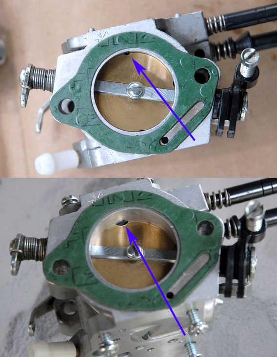
The figure below shows the throttle plate modification to improve idle
and mid-range operation. This is discussed in detail by Gerry
Farell:
http://webspace.webring.com/people/bf/flphg/idle_adaptation.html
The blue arrows show the notch before and after enlarging.
The newer carbs have done away with the purge
valve (see the figure
at the top of this page). I have found it very useful for
bleeding the fuel line, and I'm glad to have it. I understand
the
newer ones just have a hole in the metering diaphragm cover.
It
probably wouldn't be too hard to modify a cover to add a purge
valve. The pics below show how the original works.
It needs
to be able to press on the metering diaphragm/lever, without damaging
it.
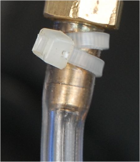
The
fuel line on many units has a 1/4" line, which can allow bubbles to
collect, especially in hot weather (fuel percolating). Even at
full throttle the fuel flow is not sufficient to move the bubbles from
a high spot in the line, where they eventually collect and slow fuel
flow enough to cause performance to decrease. A solution with
which many have reported success is to use a smaller 1/8" (~3mm) line,
which also involves removing the white plastic barb on the carb fuel
inlet. Before (top) and after(bottom) are shown below:
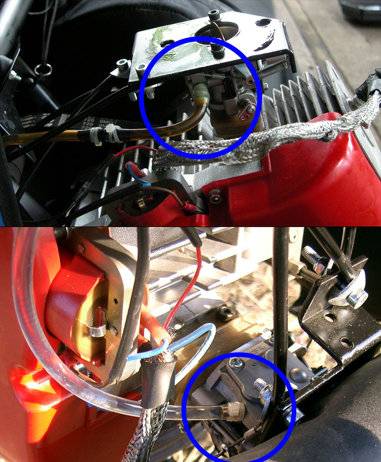
(The
silver braid is/was a failed attempt to suppress radio noise from the
ignition - resistor spark plugs are a much better solution).
I have discovered that the nylon
TyWraps work well for securing the fuel line, however, be sure to take
two wraps around the hose, as a single wrap will not apply uniform pressure all the way around.