This shows the disassembly of the electric starter that is supplied
with the Radne Aero 120.
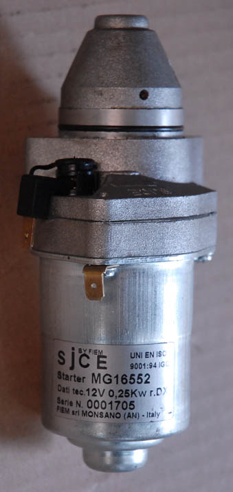
This starter is manufactured in Italy by
Fiem. It is listed
in their
PDF Catalog.
(If that link is not working, there is a
cached copy here.
The Swedish Aerosports NRG (and probably any e-start Radne) uses the
3MG16552 Model Number starter.
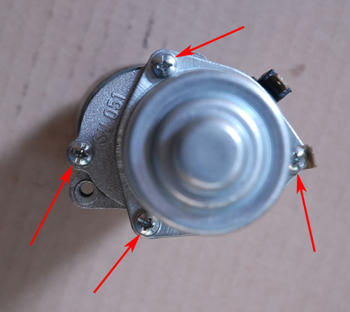
There are a total of four screws and one nut that must be removed to
disassemble the unit. This shows the 4 screws:
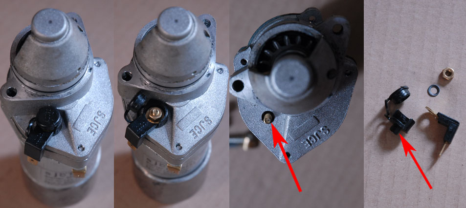
The nut that must be removed is part of the postive electrical
terminal. Pop up the protective cap that covers the terminal nut,
which will allow access to remove the nut and then the
terminal/insulator components. Note the skirt (indicated by the
red arrow in the 4th pane). This fits between the terminal stud
(red arrow in 3rd pane) and the housing, and has the important purpose
of insulating the positive terminal from the negative (ground)
terminal. Be sure this is properly reinstalled on reassembly, to
prevent a short circuit.
NOTE: I received the following helpful comment/update from Peter Mack of
Airtime Products:
On the flange of the pressed stator housing you'll find a centre punch mark near one of the holes. The motor must be re-assembled with this punch mark in the same location as it was originally or the poles will not be in the correct relation to the brushes and the motor does not spin. At least that's what I find.
You might also mention that the cap for the positive terminal insulator is glued in place these days and takes a concerted effort to get out.
With the 4 screws and terminal nut removed, the nose casting may be
removed. The Bendix gear assembly may then be lifted from the
starter motor. If you later find two washers (that may fall off
during the dissaembly), they fit on both ends of the Bendix gear.
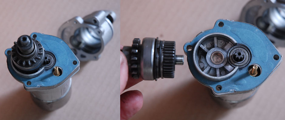
The figure below shows the complete Bendix assembly. The Bendix serves
to automatically engage and disengage the starter from the flywheel
teeth. Grasping the Bendix gear teeth (when assembled to the
starter) and rotating the gear will have two results, depending on
which direction you rotate the gear. In one direction a slip
clutch will simply allow the gear to rotate about the shaft - this is
what happens when the engine starts and the flywheel teeth are moving
faster than the starter motor can turn them. In the other
direction the Bendix gear will move outwards along the shaft, and once
it has reached the end of it's travel, further turning will turn the
shaft and starter motor.
In operation, the motor rapidly reaches full operating speed. The
Bendix assembly has a fair amount of inertia, and it is therefore
easier for it to move outwards along the shaft than it is to suddenly
rotate at the starter speed. This initial 'snap' is what causes
the starter teeth to engage the engine flywheel teeth. Once
engaged, and a load is applied between the gears, the load serves to
keep the Bendix extended. When the engine starts, the load
between the gear teeth reverses, as the flywheel teeth are now moving
faster. This causes the clutch to slip and also to push the
Bendix assembly back towards it's resting position.
Further disassembly will require compressing the spring and
removing the locking ring from the groove on the shaft. Removing
and replacing this ring was the most difficult part of the whole
procedure.
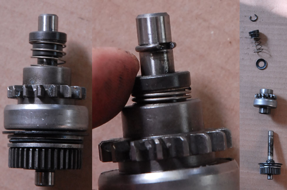
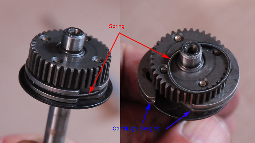
The figure below shows what appear to be
centrifugal weights. A circular spring keeps them compressed
against the shaft, and presumably, at some speed, these weights will
move outward. The left pane shows the assembled unit, the right
pane shows the spring removed and the weights moved to the outer limits
of their travel. I have been unable to figure out the purpose of
these weights, unless it is to provide some friction against the
housing and thereby help to engage the Bendix unit.
(Comment from Peter Mack:
I think the fly weights might act as a brake if the bendix remains engaged after the engine starts, forcing the bendix to disengage. They don't obviously fly out when the motor spins no load, so I'm guessing they only come out on an over-rev situation.
